The center of the spectrum is the DC component of the picture, and represents
the average color of the picture: if you calculate the IDFT of a spectrum with
only the DC component left, you get a flat image with only one color: the
average of the original image. In the program for which the code was given
above, first accept the image by pressing space, and then you can add or remove
the DC component by using the arrow keys, get the full spectrum again by
pressing the a key (or the q key on azerty keyboards), and make the spectrum
zero by pressing the m key (the , key on azerty keyboards). To get only the DC
component, first press m to remove the spectrum, then the up arrow to get only
the DC component back.
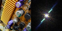
This is the original image (the bright blue line in the spectrum probably comes
from the sharp edges from the cooling fin):
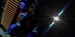
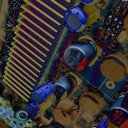
Here's the same image with the DC component removed (note the black dot in the
center of the spectrum). You can't see the whole story in fact, all the parts of
the image that look black are actually negative, since this picture represents
the original image with the average color substracted from it. On the right is
the amplitude of the image instead, which reveals the negative parts.
And here below only the DC component is left. Only a single dot remains in the
spectrum. It looks white on the computer screen, but in reality it are 3 large
floating point numbers that contain the DC color information. The DC component
of an image's spectrum is usually very large, it contains the most "energy": as
you could see on the previous image, removing this single dot from the spectrum
makes the image a whole lot darker. Energy has to be understood in terms of
Information here.
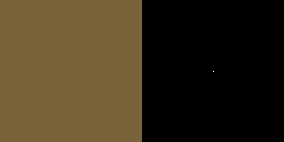
This is the average color of the image, you can call it the ultimate blur, what
you'd see if you were standing very far away from the image, or what you'd get
if you took the sum of the color of all pixels, and divided the result though
the total number of pixels.
Low
Pass Filters: Blurring
Low frequencies in an audio represent the bass of the music, but in pictures, it
represents the blurriest parts and gradients. Sharp edges and lines have high
frequencies.
An image can be blurred by, for each pixel, calculating the weighed average of
that pixel and it's neighbours, using a convolution matrix: that's the way
Photoshop and Paint Shop Pro do it, for example, you can create such a
convolution matrix with the "User Defined" filter in these programs. But, since
the convolution in the spatial domain is the same as a multiplication in the
frequency domain, we can also blur an image, by multiplying the spectrum with
the transfer function of a low pass filter. The transfer function of a low pass
filter makes all high frequency components zero or at least weakens them, while
keeping or amplifying the low frequency ones.
For very blurry blurs, a very large convolution matrix is required, and this
would require a lot of calculations. Taking the Fast Fourier Transform, then
multiplying the spectrum, and then taking the Inverse FFT, goes much faster for
heavy blurs. You can also create much nicers blurs easier and more intuitively
by using the spectrum.
The more high frequencies you remove of the spectrum, the blurrier the image,
and the more calculations would be needed in the spatial domain:

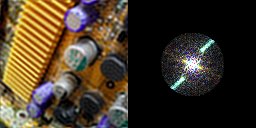
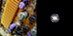
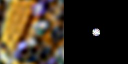
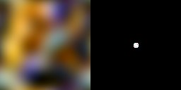

In the above images, a circular section of the spectrum is left. You can also,
for example, keep a square one, but round ones should give nicer blurs:
High
Pass Filters
A high pass filter on an image keeps only the high frequency components. Since,
by applying a high pass filter, the DC component of the spectrum is removed too,
the resulting image can have negative pixel values that can't get drawn. To
overcome this, the high pass filter of Photoshop adds 128 (half of the maximum
value 255) to each color component the resulting pixels, so grey represents
zero. Here, we'll look at the positive part of the image, the amplitude
(revealing the negative values), and the image with the DC component added again
instead.
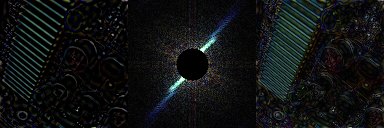
A high pass filter is exactly the opposite of the low pass filters, so now a
circular section in the center of the spectrum is removed. On the left is the
resulting positive real part of the image, in the center the spectrum with the
circle removed, and on the right the amplitude of the image:
To see much better what's going on, add the DC component to it again:
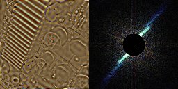
It can be seen that only the high frequency parts of the image are left: subtle
gradients and color changes are gone, only the edges of objects and especially
the cooling fin are still recognisable.
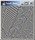
Photoshop, instead of adding the DC component, adds grey to the image to make
all pixels positive, so the result of the High Pass filter in Photoshop is
something like this:
If we use a higher radius for the removed circle, only the very highest
frequencies remain, only the cooling fin still looks pretty nice:
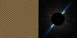
A high pass filter can also be done by first blurring the image, and then
substracting the blurred image from the original.
After seeing those pictures you might wonder if there is actually something
useful that can be done with a High Pass Filter? Well, it can for example be
used to make better tillable textures, take for example this grass texture:

If you tile it, it looks like this:
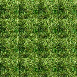
It looks pretty ugly, because there are obvious bright and dark spots in the
image, and these look very repetitive. These large areas of bright and darker
color are very low frequency components, so they can be removed with a subtle
High Pass Filter!
Let's process the image to our program, apply a High Pass filter with a very
small radius to it, and bring the DC component back: the DC component is the
lowest frequency of all, just a flat color, so it can't look repetitive, and is
very important because it contains the green color of the grass. As you can see
on the third row on the right in the screenshot, a very small circular section
of the spectrum is removed, and in the centre of the circle is a single white
point which is the DC component.
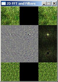
At the bottom row a new version of the grass texture appeared, that looks
already much better when tiled if you take a certain distance from it:
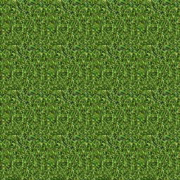
You can still recognise where the sides are, because the source image actually
wasn't a perfectly tillable one. If the source image would've been perfectly
tillable, the result would've been so as well. On a beautiful photorealistic
texture of a rocky wall, with however a large dark spot in it that makes the
rocky wall repetitive when tiled, the result of this high pass filter would've
been very useful.
The source code of the program was a little bit modified to get a high pass
filter with a smaller radius under the "SDLK_j" button.
Band
Pass Filters
Band Pass filters leave though only frequencies that are between a certain
lowest and a highest frequency. Your radio uses the 1D version of this to listen
to a station with a certain frequency. Again the DC component is removed by such
a filter, so we add it again, because without it the image is too dark to see
it. Here's the original image again, and an example of such a BP filter with DC
component:

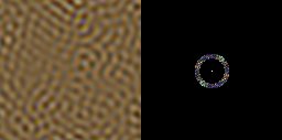
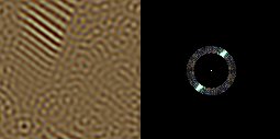
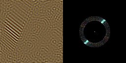
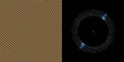
The sum of many images like this one together (but with the DC component added
only once of course) forms the original image again. Here's are a few more BP
filters, that leave through higher frequencies:
And here's the result of a much thinner BP filter, the thinner the BP filter,
the more it can be seen how the image is a sum of sine functions:
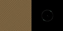
Note: not all bandpass examples are included in the program by default, but you
can easily get them by changing numbers of the BP filters in the code (under
SDLK_s and SDLK_t in the second input loop).
The Discrete
Quaternion Fourier Transform
There also exists another way of calculating the FT on colored images:
up to this point, we always calculated the FT of each channel separately, and
left the imaginary part black. This is a big loss of resources, since there are
3 unused imaginary channels. It would be nice if we could put one color channel
in the real part, and another color channel in the imaginary part. An image has
3 color components however, while a complex number has only two parts.
That's where quaternions pop up: those have 4 parts! If you don't know about
quaternions, there will come an appendix about quaternions with this tutorial,
and you can find good tutorials about them with google. You can leave one of the
4 channels zero, and use the other 3 each for one color channel. The 4th can
also be used for an alpha channel, like the transparency of the image, or IR or
UV light info.
The formulas for the 2D DQFT are:
Forward:

Inverse:

There are again multiple definitions where you divide through 1/N or 1/M or 1/sqrt(M*N)
or 1/M*N depending on which you prefer, as long as the product of those factors
of the forward and inverse version together gives 1/M*N.
e^i and e^j can again be converted to cos and sin with the formula of the
exponential of imaginary numbers, and i*j=k. Note that quaternions aren't
commutative, so the order of multiplication is important! With this information
you should be able to code a 2D DQFT or DQFFT function, an example might follow
later.
For images with more than 4 channels, you can of course define a Discrete
Octonion Fourier Transform, etc... :)
